|
KIT
Never
having made a vac form kit , the task was approached
with some misgivings, but
having purchased the kit some 10
years previously because it looked so good ,I felt that
I really had to have a stab at it .
I'd
made some models many years ago ,not taking the whole thing too seriously,
but
had recently joined a model club for the first time . Some of the models shown
there
were so far ahead of anything I'd ever made or seen , that I was inspired to try
and make something too ,and after
all,I had a kit at home that I could have a bash at rather than throw it away.
So
the Swift became the guinea pig and my vac form experience was limited to
looking at the kit in a plastic
bag. It looked like a good
starter as it had some white metal bits ,thereby saving me the job of making
them and the major parts appeared to have good shape and detail, with the
plastic being of a good thickness. The kit plan
had some sketches of certain sections to help with adding
detail.
I'd
found some colour illustrations in
an old aviation magazine, applicable to the subject ,showing the squadron
markings and camouflage .
A
ball point pen was used to first outline the major parts, all panel lines were
engraved, then all of the numerous flush
intakes as well as the camera windows were opened up.
The
major parts were cut out and sanded down to the Biro line, finding out in the
process just how flexible the parts were now. It was clear that some
formers and/or bulkheads would be necessary to stiffen the structure
and enable it to be squared up.
|
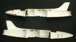
Fuselage
A
5mm strip was superglued into one half along the length of the mating
edges to enable a strong joint ,and also helping to make joining the
halves a bit easier. Several bulkheads had been made , in halves ,( so
that they would overlap when the fuselage halves were joined), and glued
in with numerous small gussets ensuring that they were square.
The
nose wheel well was detailed using some ribs and imagination. Cannon ports
were drilled out, plastic tubing inserted so that some metal tube barrels
could be slid in later. |
|
Small
plastic blocks were glued into the rear fuselage to give a strong mounting
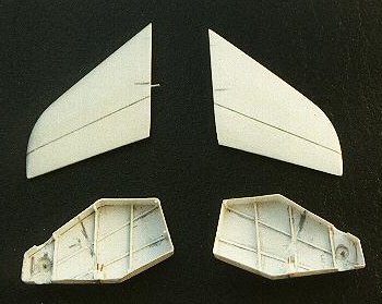
for the tailplanes.
The
flush intakes which had been opened ,were blanked off internally using
thin, black painted card. The small but prominent scoops on top of the
fuselage were filed up from scrap plastic, and fitted. The tailpipe
assembly was to be fitted after joining of the fuselage halves ,through
the bottom prior to fitting of the wing assembly. A dummy turbine
disc and exhaust cone were made up according to some
sketches
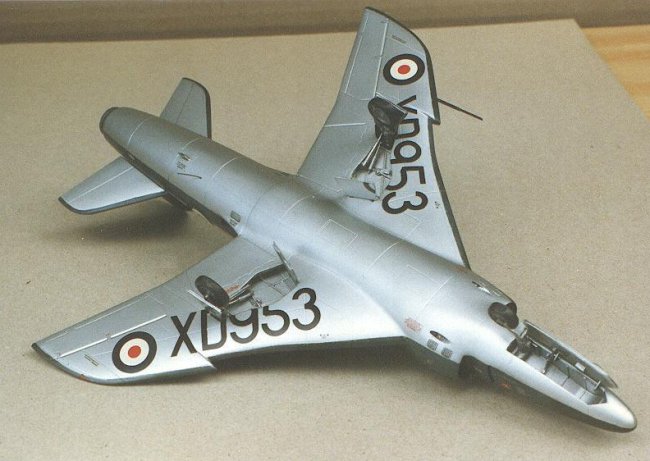
made previously . The kit supplied alternative noses for both
FR5 and FR6 versions, as well as
increased span wingtips for
the FR6. |
|
Click on
image below to see larger image |
 |
|
|
The
correct nose sections were added to each fuselage half, merged in with
filler and then the intakes carefully opened out, and the edges smoothed. |
|
Wings
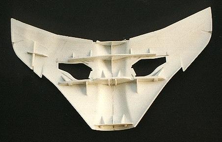
The
wheel wells were given some imaginary detail and the apertures in the
wings opened. The one piece lower wing, though fairly large and deep
,was even more flexible than the fuselage, so a couple of spars were made
from thick card and fitted,
with plenty of gussets to keep them square. A piece of plastic tube was
fitted on the port side to take the beefy
pitot tube later, and the wheel wells glued in place.
New
main u/c doors were scratchbuilt
from card and detailed with the help of the sketches provided , and
the kit
nosewheel door given
some detail as well.
The
stabilisers were assembled and a wire inserted to enable them to be fitted
into pre drilled holes.
|
|
Click on
image below to see larger image |
 |
 |
|
|
Cockpit
|
|
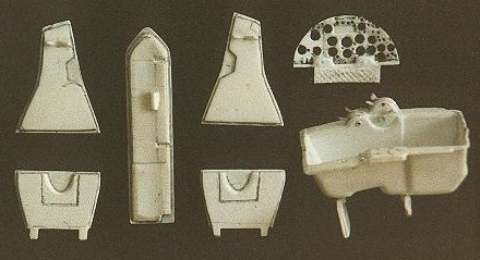
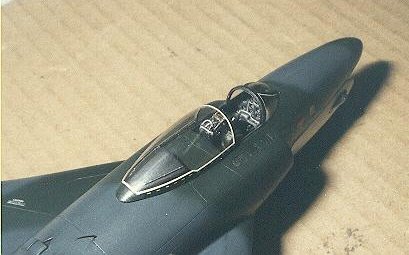
The
kit cockpit tub was used. Levers and other controls simulated by
referring to the sketches on the plan sheet. The instrument panel
was drilled out ,dial faces scratched onto thin ,black painted card and a
clear film sandwiched between the two . I had used the 3 layer method
without knowing there was such a thing, but have since read that it's not
an uncommon procedure.
The
metal ejection seat had a blind handle and side guards added, seat belts
made and fitted .
Cockpit
side panels and consoles were
scratchbuilt referring to the plan sketches, a control column as well as a
gunsight fabricated and fitted and
the whole cockpit finished in Testor's Exhaust which I now always
use as a convincing scale
black. |
|
Click on
image below to see larger image |
 |
|
|
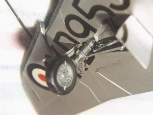
Undercarriage
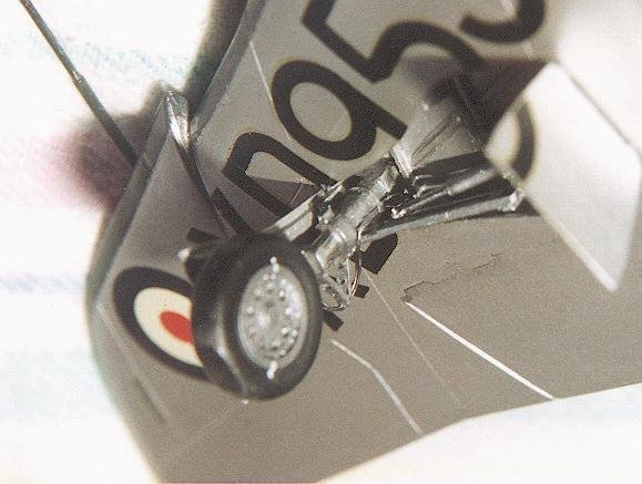
The
white metal items were cleaned up ,thin wire brake lines added , and side
stays with jack scratchbuilt using the kit sketches as a guide. The
nose leg was cut off and a wire pin inserted enabling it to be turned
slightly. |
|
Click on
image below to see larger image |
|
|
Minor
details
The
large pitot tube was simulated using two diameters of brass tube ,then inserted
into the tube previously provided in the wing.
The
fuel vent was made from a piece of flattened drinking straw and whip antennae
from paint brush bristles.
Camera
windows were made from Kristal Kleer.
The
white canopy framing made using
thin strips of decal sheet and the break in
dotted lines from smaller lengths of yellow decal.
Final
assembly
The
wing tops were mated to the fuselage sides, flange to flange, with superglue and
clamped till really set.
Test
fitting of the wing bottom allowed the correct fuselage width to be found so
that when the wing was added, top and bottom wings would fit . Having found this
width, the overlapping bulkhead halves were glued together to maintain it.
When
the wing bottom was put in place, it fitted perfectly and the joint lines were
easily filled. Small blocks of clear runner were superglued into the cutouts
made in the wing tips for the nav lights ,and when the whole assembly was dry,
were wet sanded to conform with the tip shape and polished clear again.
|
Click on
images below to see larger images
|
|
 |
 |
 |
Finishing
After
assembling everything to make a whole model ,all surfaces were wet sanded very
smooth, and a thin coat of grey primer sprayed on to reveal any defects which
were then rectified.
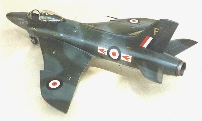
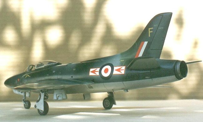
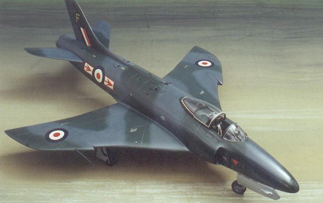
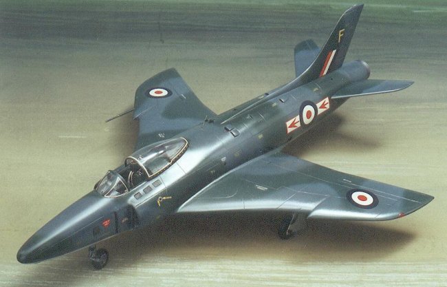
The
RAF scheme of the time was Dark green, Ocean Grey camouflage with
Silver undersides . The kit roundels were used ,but slightly larger red centres
had to be fitted to cover the out of register originals . The large underwing
serials were applied with the wheel doors in place and trimmed when almost dry.
The
squadron marking supplied in the kit was White bars/Black arrows, but as the
magazine photos clearly showed White bars with Red outlines and Red arrows, new
markings were cut from Red and White decal sheets to match the illustrations.
The
letter "F" was cut from decal sheet ,as the photo showed
that it was upright and not swept back.
No
stencilling had been supplied , and photos showed that most on the upper surface
was in YELLOW! I ratted every small yellow item I could find
to get enough to be reasonable, but more would have been
preferable. If you've ever looked for stencilling in yellow, you'll know
how scarce it is. Fortunately, it's small enough not to be easily legible,
as there would be some strange
instructions applied
in strange places . The metal wheels and u/c legs were fitted and doors
attached. The metal ejection seat had just enough weight to prevent a
tailsitter, without the need for ballast.
|
Click on
images below to see larger images
|
|

|
 |
 |
|
Photos by Pieter Stroethoff |
Conclusion
The
final result reasonably resembles a Swift ,with the only uncorrectable problem
being the excessive wing root
thickness, which isn't that bad as it is only obvious from certain viewpoints.
The main positive gained is that vac forms are not
that scary after all and felt that I
might tackle more in future, if they're all as well thought out as this
one.
My
appreciation must go to Pieter
Stroethoff whose photos of the finished model
make it appear better than it really is.
Allan
|
|